Today, Positive Motion Technology will share with you the application of C++ to develop a motion control routine for laser galvanometer.
We mainly start with creating a new MFC project, adding a function library, and finally explain the actual project-laser galvanometer marking routines to familiarize everyone with its project development.
Before the formal study, we first understand the motion controller ZMC420SCAN of positive motion technology. This product is a 20-axis motion controller.
ZMC420SCAN bus controller supports ECAT/RTEX bus connection, supports up to 20 axis motion control, supports linear interpolation, arbitrary arc interpolation, spatial arc, spiral interpolation, electronic cam, electronic gear, synchronous follow, virtual axis setting Etc.; Real-time motion control can be realized by using optimized network communication protocol.
ZMC420SCAN bus controller supports mixed interpolation of pulse axis/bus axis/galvanometer axis.
ZMC420SCAN supports 10 channels of pulse output and encoder feedback and supports 4 channels of galvanometer axis, onboard 24 input, 12 output, 2AD, 2DA, all output ports support high-speed PWM control.
The wiring method is shown in Figure 1 below:
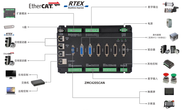
ZMC420SCAN uses a set of API functions, supports C, C++, C#, LabVIEW, Python, Delphi and other development languages, supports VC6.0, VB6.0, Qt, .Net and other platforms, supports Windows, Linux, WinCE, iMac and other operating systems .
圖2
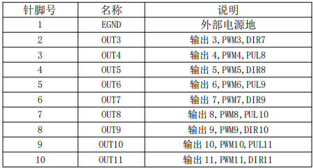
The PWM output of ZMC420SCAN is controlled by the normal output function. The PWM output can only be performed when the output port is "ON", which is convenient for controlling laser energy.
The output 0-7 of ZMC420SCAN has the function of precise output. The precise output function of each output is independent of each other. Through MOVEOP_DELAY and AXIS_ZSET, you can set whether each MOVE_OP instruction uses precise output and the delay of precise output, so as to realize the laser PSO control.
The output 0-7 of ZMC420SCAN supports precise output and is independent of each other. Through commands: MOVE_OP, AXIS_ZSET, MOVEOP_DELAY to control the laser switch, precise output switch and delay, so as to realize the laser PSO control.
ZMC420SCAN supports XY2-100 galvanometer protocol, supports motion control and galvanometer joint interpolation movement.
The host computer is connected with the controller through the network port, and obtains the handle of the corresponding controller, controls the galvanometer axis through the XY2-100 protocol, and controls the servo or stepping axis through the bus protocol or pulse mode.
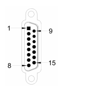
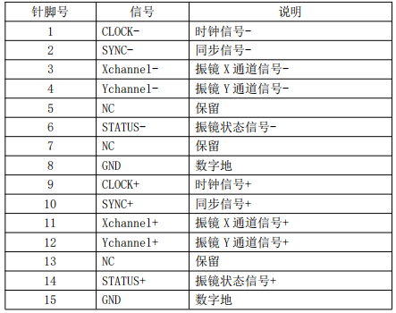
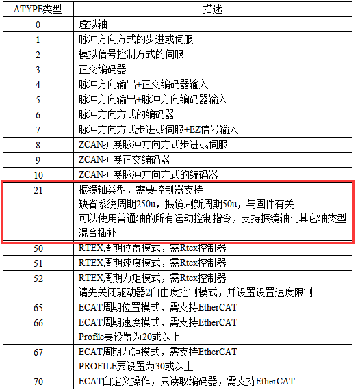
The local axis number 4/5 can be configured as the first galvanometer with ATYPE=21, and the local axis number 6/7 can be configured as the second galvanometer with ATYPE=21, and the axis number can be configured through AXIS_ADDRESS.The following is the development process of laser galvanometer control
New MFC project Add function library
1. In the VS2017 menu "File" → "New" → "Project", start the project creation wizard.

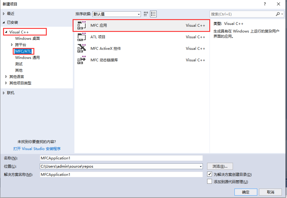
2. Select the development language as "Visual C++" and "MFC Application" in the program type "MFC/ATL".
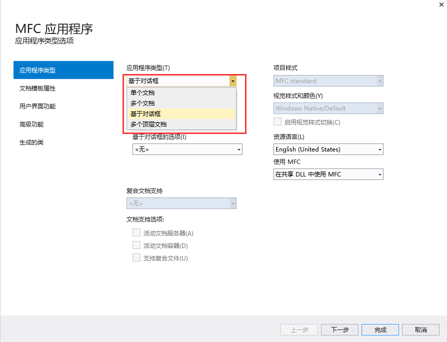
3. Select the type as "Dialog-based", next or finish. The next step is to continue the configuration, and just complete it directly. Select the type, and the others can be edited in the project.
4. Find the CD-ROM data provided by the manufacturer, the path is as follows (64-bit library as an example):
A. Enter the CD data to find the PC function folder.
B. Select function library 2.1.
C. Windows platform.

D. Select the corresponding function library according to your needs. Here, select the 64-bit library.
E. Decompress the C++ compressed package, which contains the C++ corresponding function library.
F. The specific path of the function library is as follows.

5. Copy the C++ library files and related header files provided by the manufacturer to the newly created project.
6. Add static libraries and related header files to the project.
Static libraries: zauxdll.lib, zmotion.lib
Related header files: zauxdll2.h, zmotion.h
A. First right-click the header file, and then select: "Add" → "Existing Item".
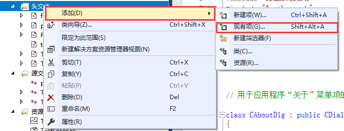
B. In the pop-up window, add static libraries and related header files in turn.

7. Declare the header file used and define the controller connection handle.
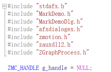
At this point, the new project is completed.
Check the PC function manual to understand its usage
1. The PC function manual is also in the CD-ROM, the specific path is as follows:

2. PC programming, generally first select the corresponding connection function to connect to the controller according to the controller connection mode, and return the controller handle. Then use the returned controller handle to control the controller.
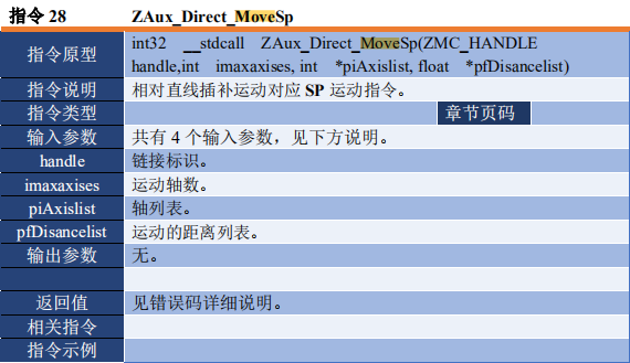
3. For example, to connect the controller through the network port, first use ZAux_OpenEth() to link the controller to obtain the controller handle.
4. Set the laser galvanometer axis type to the controller through the acquired controller handle.

The value of the third parameter has the following mode selections. To use the galvanometer axis, you need to select the axis type 21 mode. Set the axis to the galvanometer axis type. The system cycle and refresh cycle of the galvanometer axis type are much faster than the ordinary axis.
5. Through the acquired controller handle, the galvo axis of the controller is controlled to perform multi-axis motion control, and the galvanometer axis can be matched with the ordinary axis for mixed interpolation motion.
